
- Polyester Capacitors>
- Polypropylene Capacitors>
- Polystyrene Capacitors>
- Polycarbonate Capacitors>
- Polyphenylene Sulfide Capacitors>
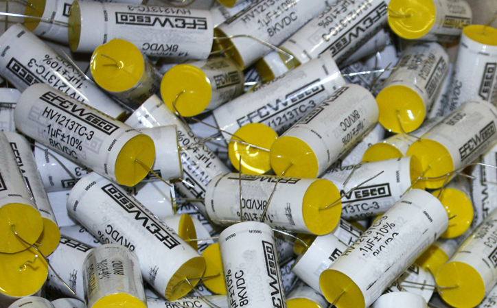
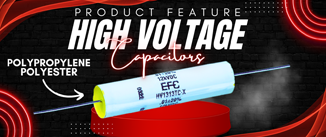
- High Voltage Capacitors>
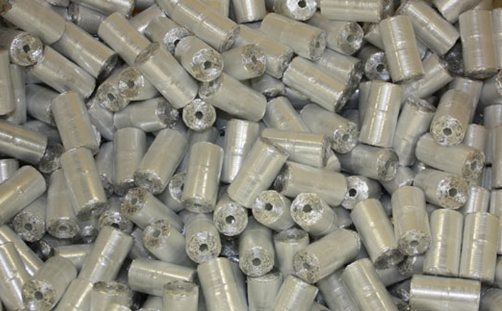
- Power Capacitors>
- DC Link Capacitors>
- Product Catalog (Rev 22)>
 KNOWLEDGEABLE
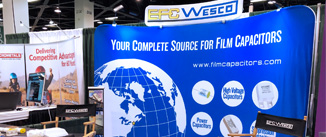
Film Capacitor Manufacturer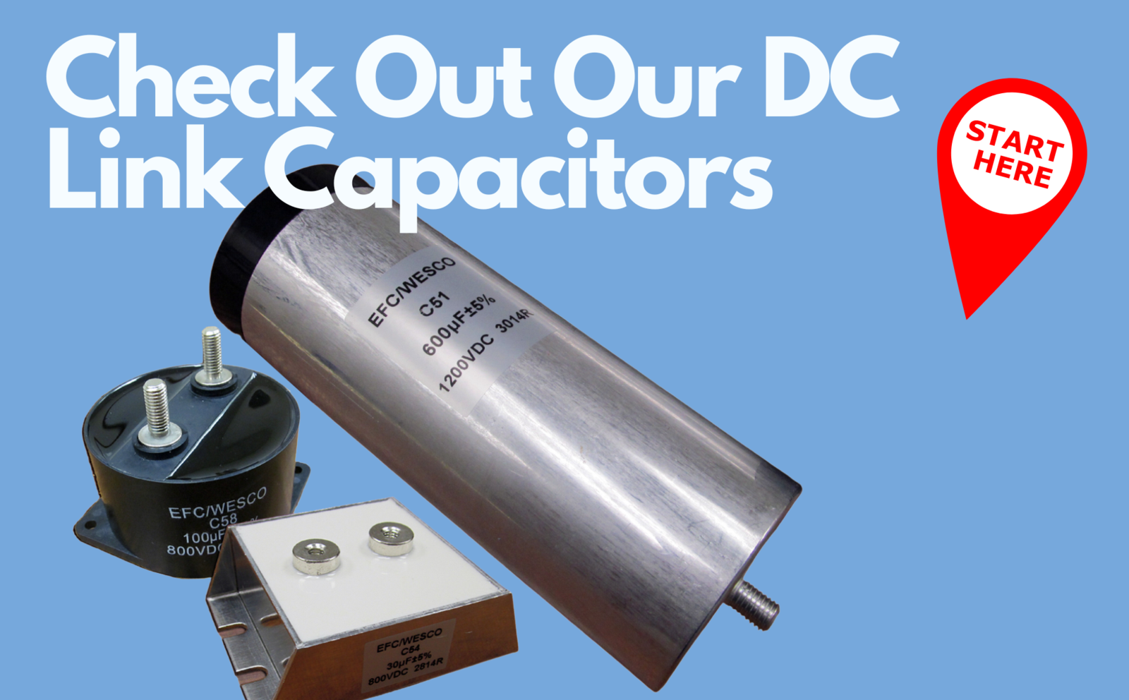
.png)

WHAT’S HAPPENING?
Your one stop for the latest news and events! Also, be sure to follow us on social media for up to the minute updates on your friends at EFC/Wesco!
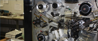
OUR PROCESS
Where can you find a custom capacitor manufacturer with outstanding customer service oriented staff, with a vast and ever changing product portfolio, and industry leading production lead times?
FEATURED PRODUCTS
Interested in a high voltage capacitor? Click here to watch a video detailing the features and benefits of EFC/Wesco's high voltage series of capacitors for your next design.


